Introduction to GPU
In almost every computer there is a Graphic Processing Unit (GPU). It is responsible for displaying everything to the screen, but it can also accelerate some processes linked to the display.
This article focuses on how the acceleration of the GPU works when displaying objects defined in 3D, also called 3D rendering.
What the GPU can do?
A GPU contains a lot of hardware and software functionalities. Among these functionalities, two main ones define a GPU as “good about doing 3D rendering”:
-
Floating point arithmetic and computation (following the IEEE 754 specification): The GPU is efficient to do linear algebra computations, i.e.: vector or matrix computations. It is common to specify the raw power of a GPU with its amount of FLoating point Operation Per Second (FLOPS).
-
Ability to subdivide triangles into pixels (called rasterization): The GPU is efficient into subdividing triangles into pixels and drawing them on an image, i.e. filling triangles with pixels. So, another way to specify the raw power of a GPU is the pixel/texel fillrate per second, i.e.: how fast a GPU can fill and color pixels per second.
The GPU can also display lines (as segments, from one point to another) and single points. For the sake of simplicity, the rest of this article only speaks about triangles.
Although these two features are coming from the need to accelerate 3D rendering, you can use them for more generic purposes. That’s why, today, the GPU can accelerate as well other algorithms (like mathematical ones) or even the display of 2D GUI.
Internals of a GPU: a legacy constraint
The evolution of 3D rendering algorithms has a big influence on how a GPU works internally.
For a long time, the GPU was the equivalent of a Field-Programmable Gate Array (FPGA), i.e.: a processor specialized in the acceleration of specific 3D rendering API like OpenGL.
Then the evolution of rendering API progressively opened the internals of the GPU, to make it more flexible and being able to accelerate different 3D rendering algorithms.
However, the spine of real time 3D rendering, called the rendering pipeline, remains somewhat fixed due to these legacy constraints.
Rendering pipeline
The rendering pipeline consists in three main steps:
-
Vertices creation: The place where the GPU creates vertices to be able to build triangles in the next step. These vertices should have coordinates in a 3D space adapted to project geometry, i.e.: a homogeneous coordinate system (x, y, z, w).
-
Triangles assembly and rasterization: During this operation, the GPU builds triangles and generates a list of pixels for each ot these triangle. This is a software and/or hardware fixed operation with a prefined number of separate steps. Each of these steps has parameters to control its behavior.
-
Coloring the pixels (called shading): After the subdivision of all the triangles into pixels, it is possible to control exactly what will be the color of each of these pixels before the GPU writes them into the image.
These 3 steps are always done in the same order to draw each 3D object (or group of 3D objects) into the image.
It does not matter how you define these 3D objects, you have to triangulate theses 3D objects (i.e.: transforms them into triangles), one way or the other, to be able to use the power of the GPU for 3D rendering.
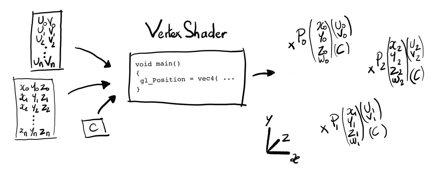
1. Creating vertices (Vertex Shader)
The first step of the rendering is to create vertices for the GPU to be able to build triangles for the next step of the rendering.
This step is configurable by setting a specific program for it: the Vertex Shader program. The GPU executes this program for each vertex it is waiting for.
The total count of vertices the GPU is waiting for depends from the number of triangles that it needs to draw and the number of vertices per triangle that it needs to create, according to the topological model chosen.
For example: in the case of a simple topological model of 3 vertices per triangle, if you set the GPU to draw 9 triangles, then it waits for 9 x 3 = 27 vertices for the rendering. As a result the GPU is going to execute the Vertex Shader program 27 times.
It is possible to configure and specify the data the Vertex Shader program uses as input for each execution (i.e.: for each vertex), with two type of data:
-
Read only global data: This data is not going to change between each vertex (for example: the uniform type in OpenGL).
-
Dynamic and iterative data: A set of specific values attached to each vertex. If this values may be different from one vertex to another, they are always organized and structured the same way (i.e.: memory wise) for all the vertices of a same 3D object. For example: if you configure 2 float values for a vertex, then each vertex data should have 2 float values defined when the GPU executes the Vertex Shader.
The necessary and mandatory output data of a Vertex Shader program is the vertex position. This position is in a 3-dimensional homogeneous space (x, y, z, w): the clip-space. The GPU needs these positions in order to build triangles for the next step of the rendering pipeline.
The Vertex Shader program can also output additional data for each vertex. The GPU forwards these additional data to the other steps of the rendering pipeline. For example, the Vertex Shader program can also output a color or a texture coordinate for each vertex it creates.
As a side note, with the progressive opening of the rendering pipeline through new API, it is possible now to control the way the GPU builds the triangles with other specific programs (i.e.: to control the triangle topology). For example, it is possible to build new triangles from triangles, in a recursive way (with some limits), like in the tessellation process.
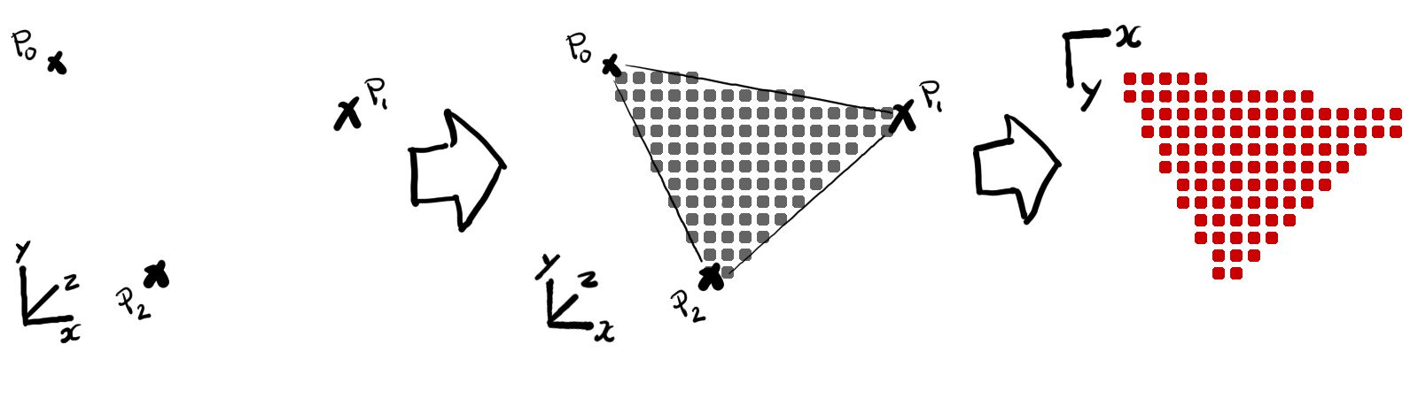
2. Building and rasterizing triangles (Rasterization)
The second step of the rendering pipeline is to build triangles and to generate a list of the pixels of all vertices previously created.
The first process is to regroup all created vertices from previous step to build triangles, according to the topological model chosen.
Then these triangles are transformed from the homogeneous space (called the clip-space) to a normalized device coordinate space, and finally into the screen space. The screen space matches the 2 dimensional space of the rendered image.
The goal of all of these transforms is to test the triangles to optimize the pixels generation, i.e.: to generate the ones that are visible.
Some of these tests are mandatory, like checking if a triangle is inside the image’s borders. Others are optional and configurable, like the selection of certain triangles based on their winding for example.
Finally, for the triangles which have successfully passed all the tests, the GPU rasterizes (or subdivides) them as a list of pixels to draw.
During the generation of the pixel list, the GPU forwards, with each pixel, additional data attached to the vertices (during execution of the Vertex Shader program).
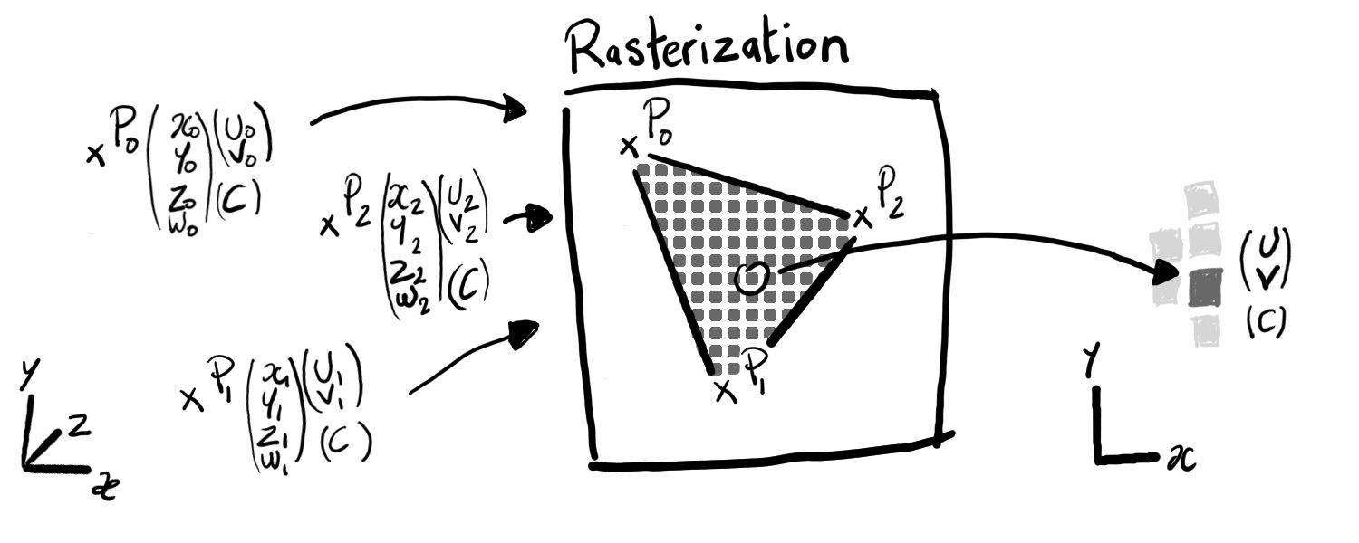
The GPU may generate a lot of pixels from only 3 vertices of a triangle, so it has strategies to forward this additional data with pixels. The default strategy is to weight each vertex of the triangle and interpolate the data between the vertices according to the position of the pixel inside the triangle. Another strategy is the simple copy of the data attached to the main vertex of the triangle (usually, any API lets you define the main vertex of a triangle).
Finally, the GPU forwards this pixel list and their respective data to the next step of the rendering pipeline.
3. Coloring pixels (Pixel/Fragment Shader)
In this last step, the GPU puts all the pixels of the triangles into the image.
In the same way during the vertices creation, it is possible to configure fully this step by setting a program, called Pixel/Fragment Shader program, which is going to tell the color of each pixel, in RGBA format.
The GPU executes this program for each pixel in the pixel list.
The previously attached data, output of the Vertex Shader program, passed from the rasterization step, is part of the inputs of this program.
Another input are images, defined through textures and samplers. These images are usually used during this step to get material information for each pixel (like color, shininess, etc.).
The output of the Pixel/Fragment Shader program is a color, the color of the pixel that the GPU executes the program for, and which is going into the image.